At some point, everyone attempting to fix electronics ends up making one. I’ve been messing about with my old Mac LC, replacing capacitors on the logic board, in the power supply, and most recently the 12inch RGB Display. I got away without using one of these when working on the Mac power supply, but powering the display for the first time instantly blew a fuse. After the repair, its time to try again, but to avoid blowing more fuses – enter the dim bulb/ limiter.
There are many explanations around the web on how to make one and how it works. In short(!) it protects a device under test from a short circuit fault indicated by the dim bulb shining bright and continuous, and so, limits the current in the circuit based on the Wattage of the combined load. There’s a good in depth explanation from the Learn Electronics Repair channel on YouTube.
I am using a similar design to that, made of domestic electrical components – no intricate electronics.
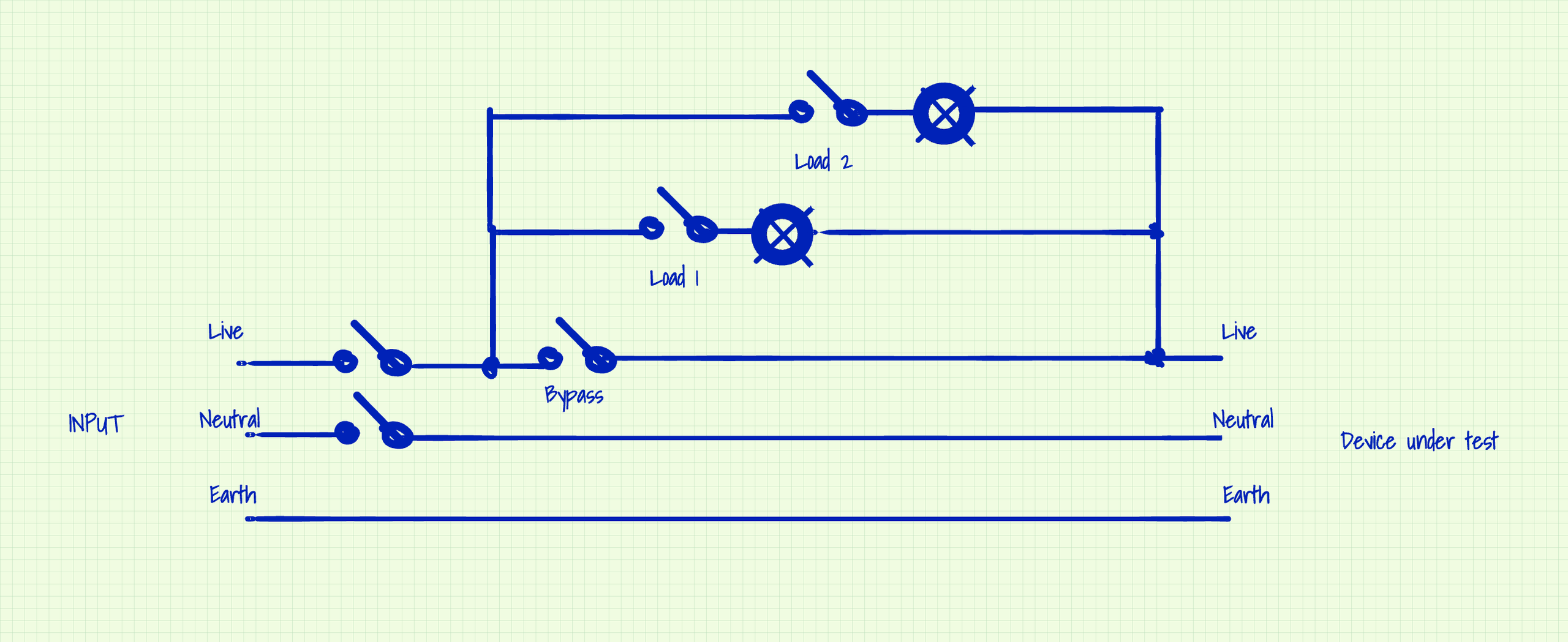
With a junction box, a short, one gang extension, incandescent bulbs and a few switches, I implemented the above diagram.
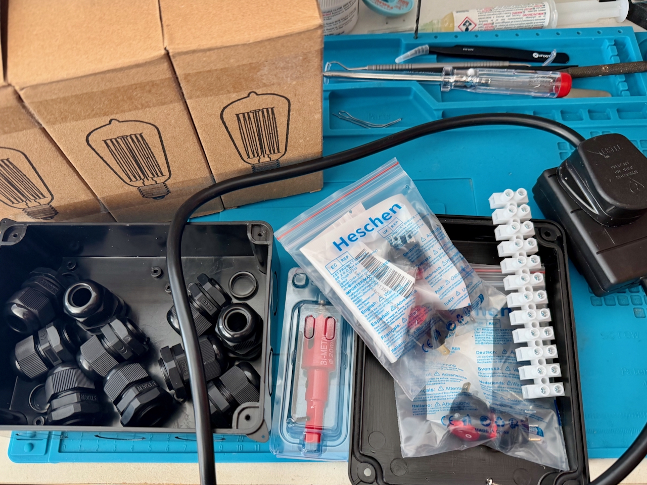
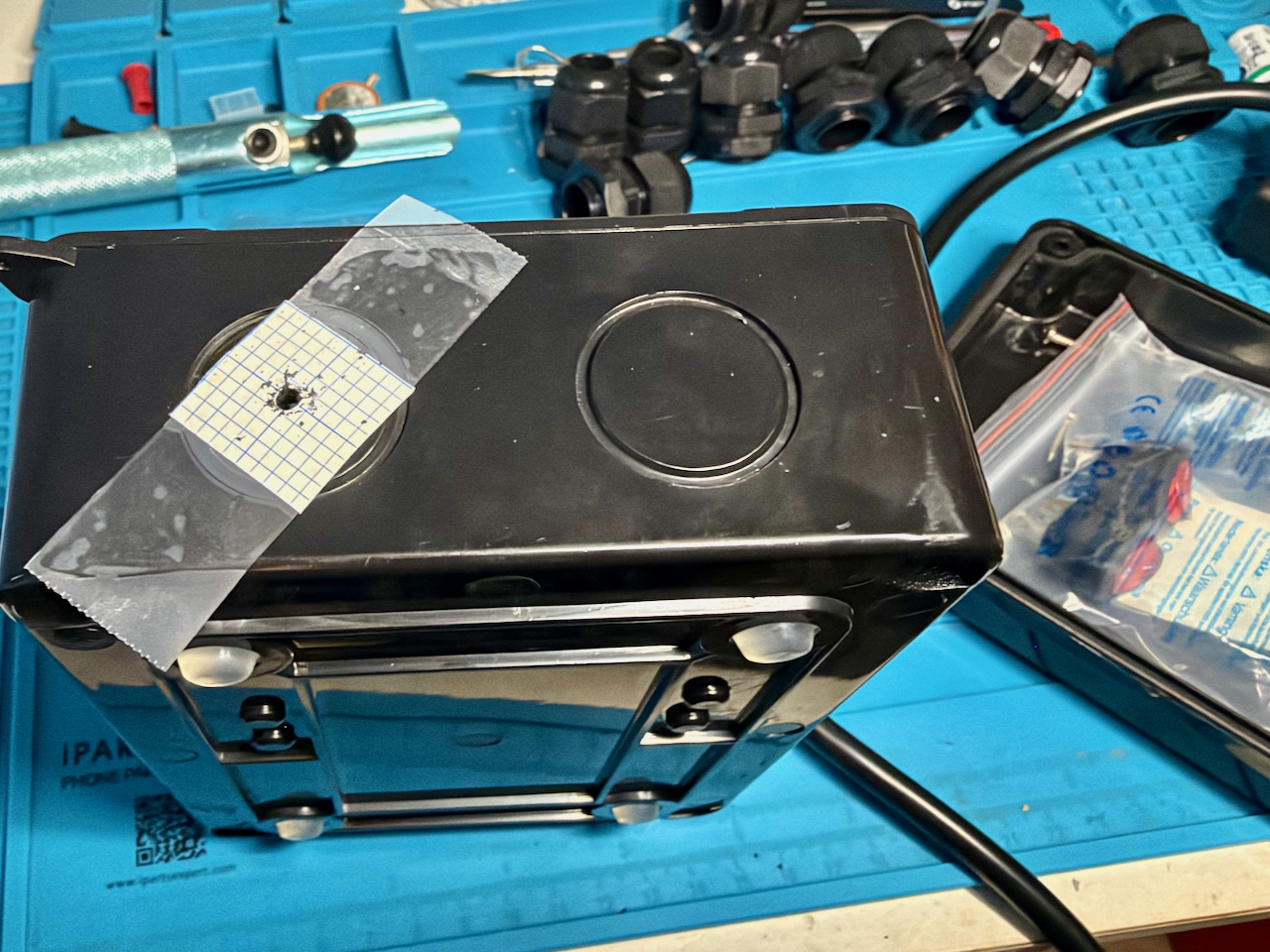
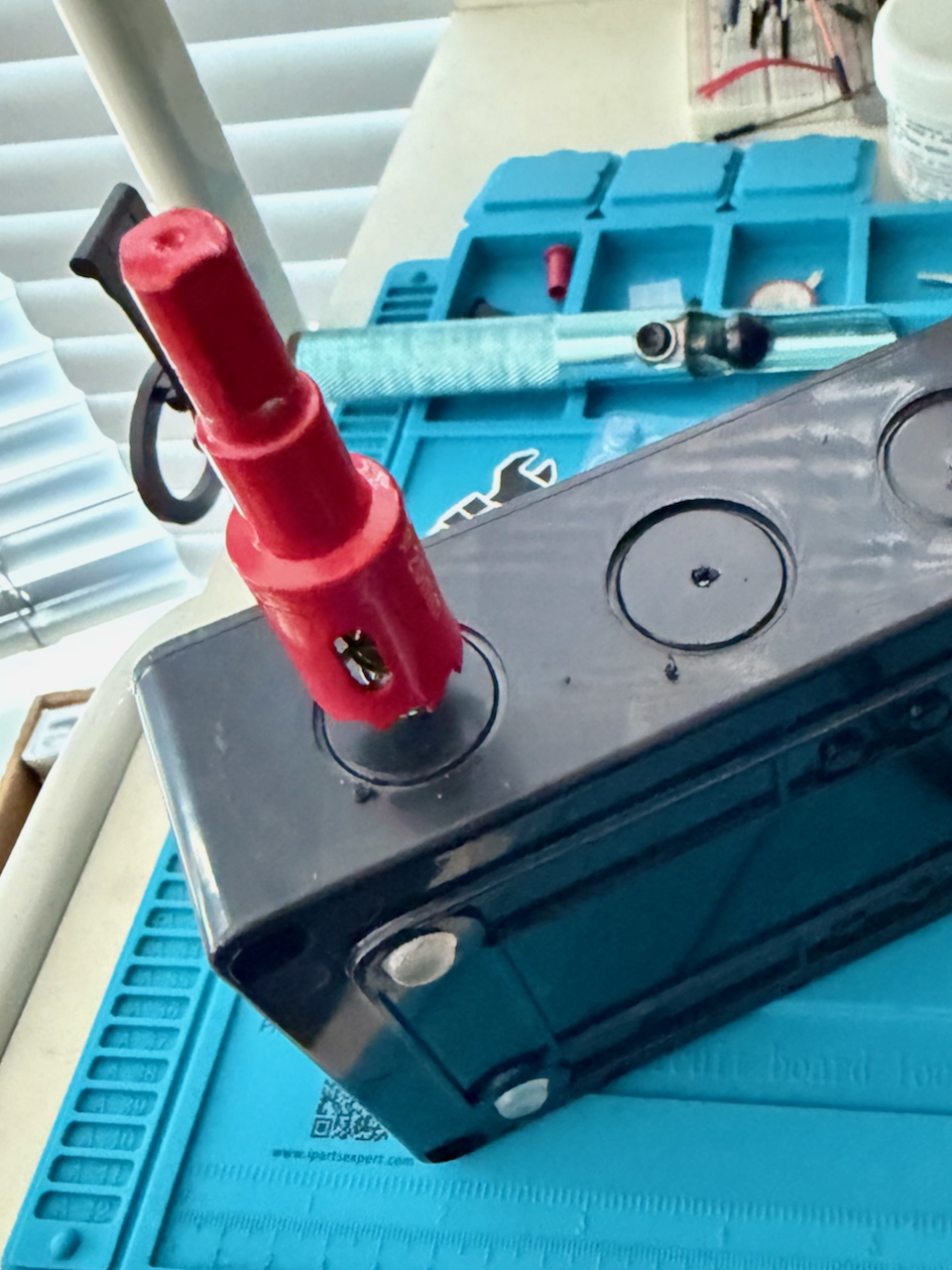
First job was to cut the 20mm holes in the junction box for the switches, power in and out, and a smaller hole to the lamp holders on the lid. I used a 20mm square of graph paper to locate the centre point, then used a centre punch and small pilot hole drilled with my refurbished Black and Decker. Then, since I don’t have a workbench or vice, I cut the rest of the hole with the Bi-Metal cutter by hand, turning with a small spanner.
Wired up and fitted the lamp holders. Stripped the outer insulation from the middle of the extension lead–we are going to keep the earth core intact.
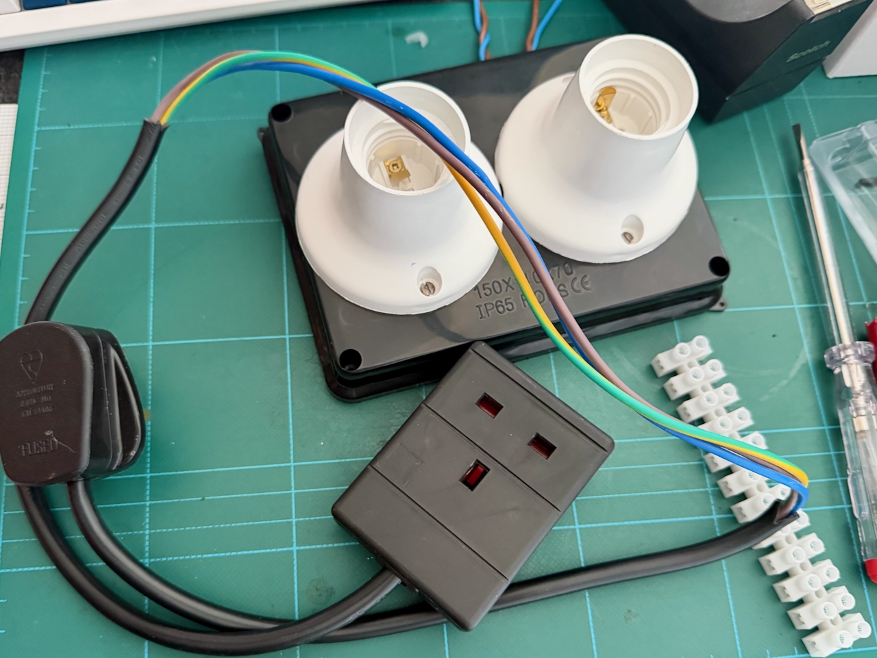
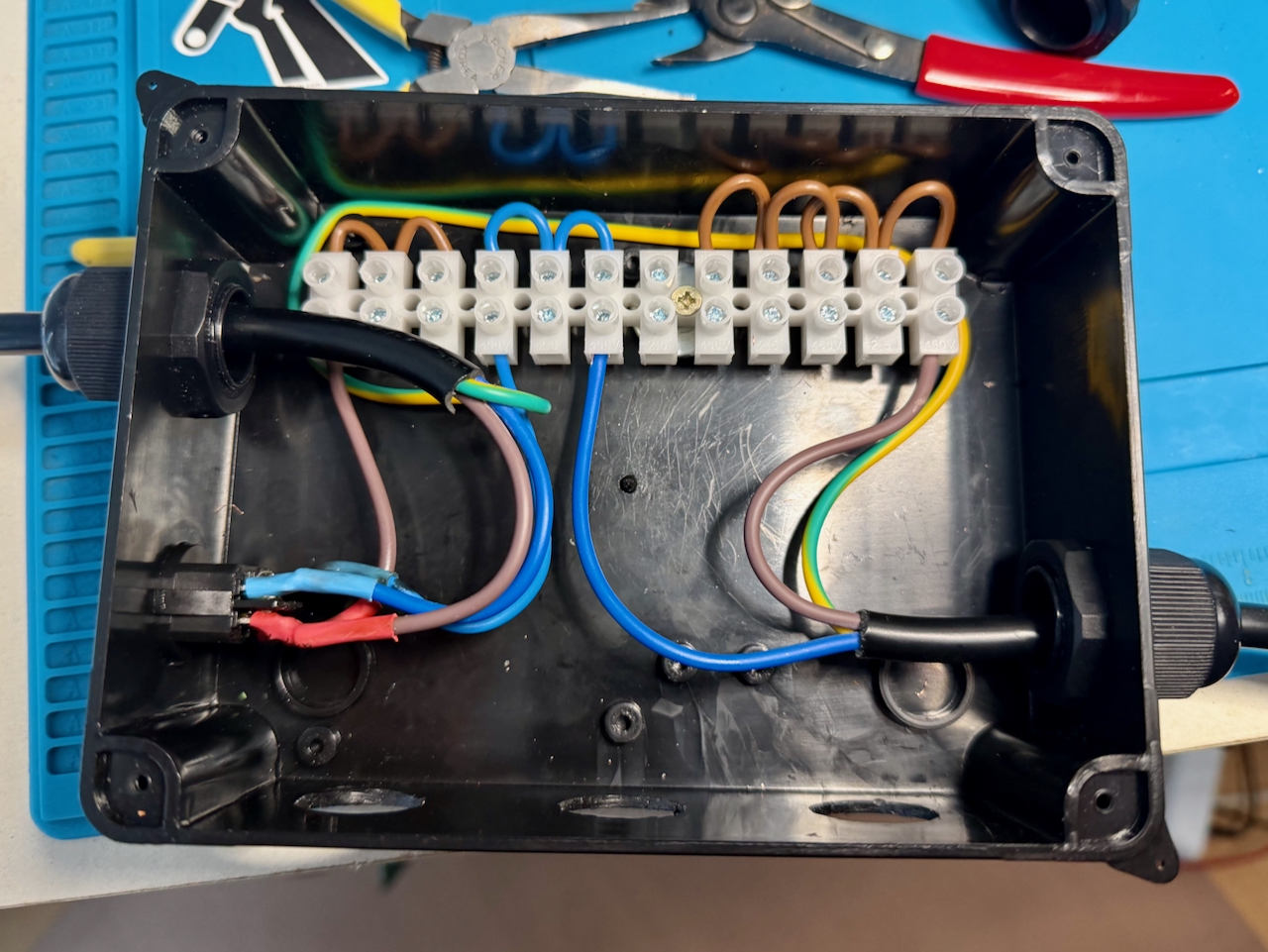
Divided the connection strip into three regions of grouped connections, from left to right:
- Live In
- Neutral
- Live Out
Fixed the connection strip in-place and wired in the main on/off switch and connect the extension’s Live In, Neutral, and Live Out to the strip. Routing the intact earth wire out of the way.
The reason the Neutral has been added to the connection block is to allow the illumination of the load and bypass switches, which each have a 3rd terminal to neutral for their internal bulb.
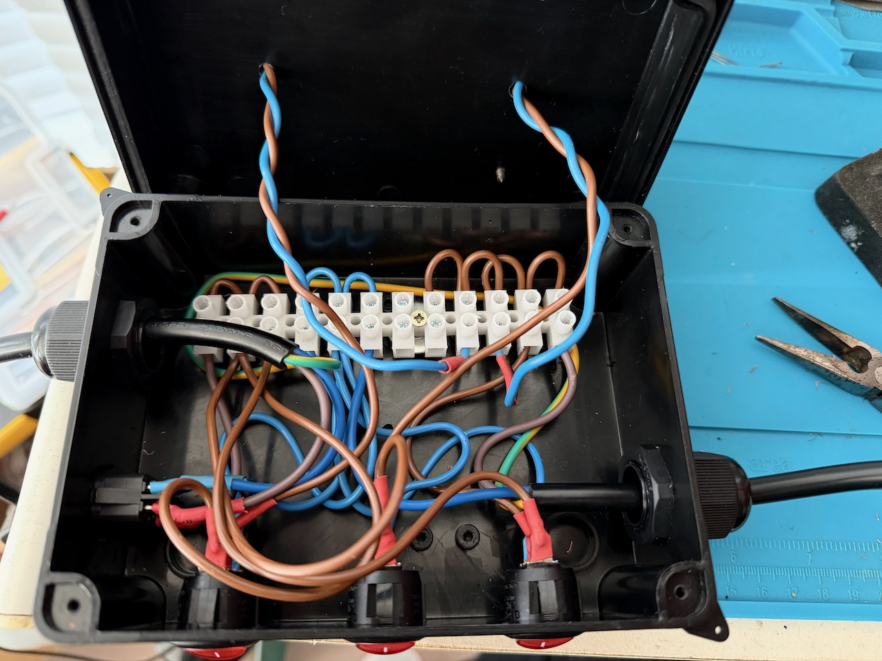
It does look a bit of a nest once the three switches and two bulbs are wired in, and I should probably have moved the main switch to the back, to have better clearance with the switch for load 1.
After all switch combinations have been tested its time to add the bulb and check the display for a fault, and with a steady bright light, there’s still a short to be investigated.
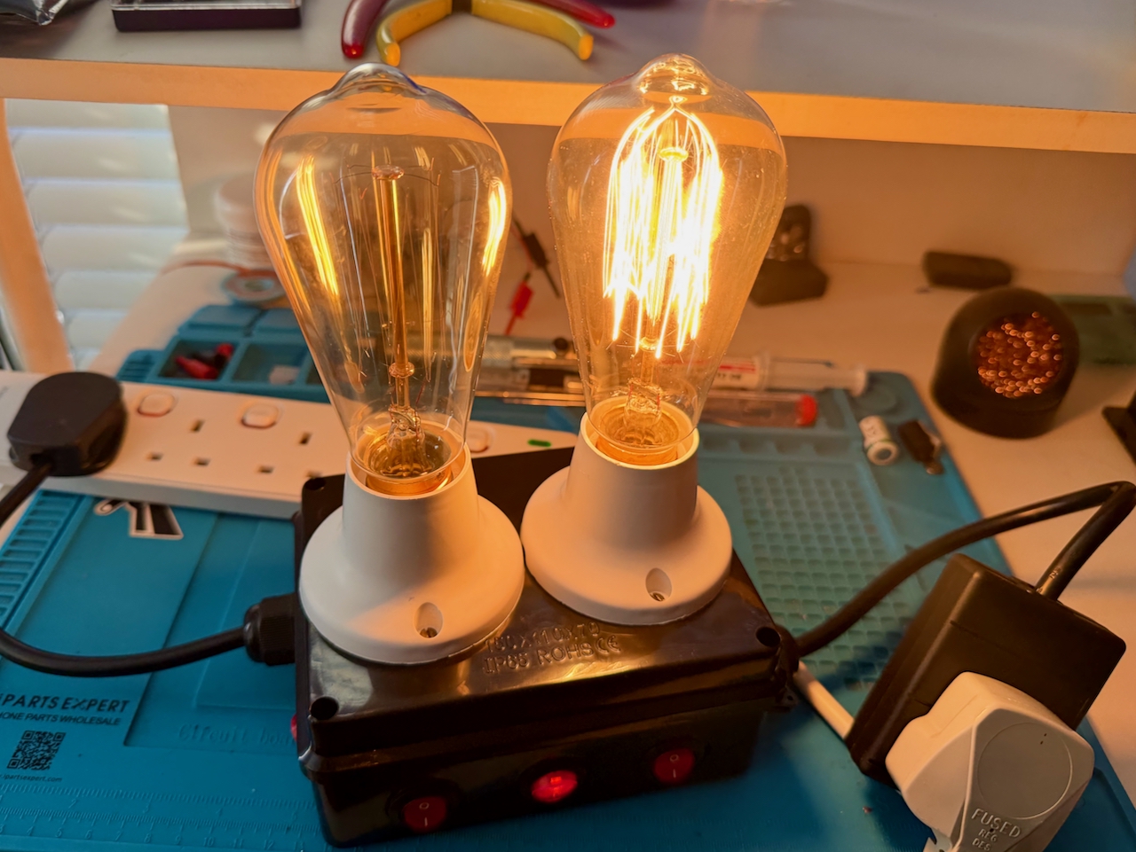
It looks, and I guess is, more ‘retro’ than the vintage computers I am working on.
