Repair

Mains cord replacement on Black and Decker Super D500 turned into a bigger job

Introduction

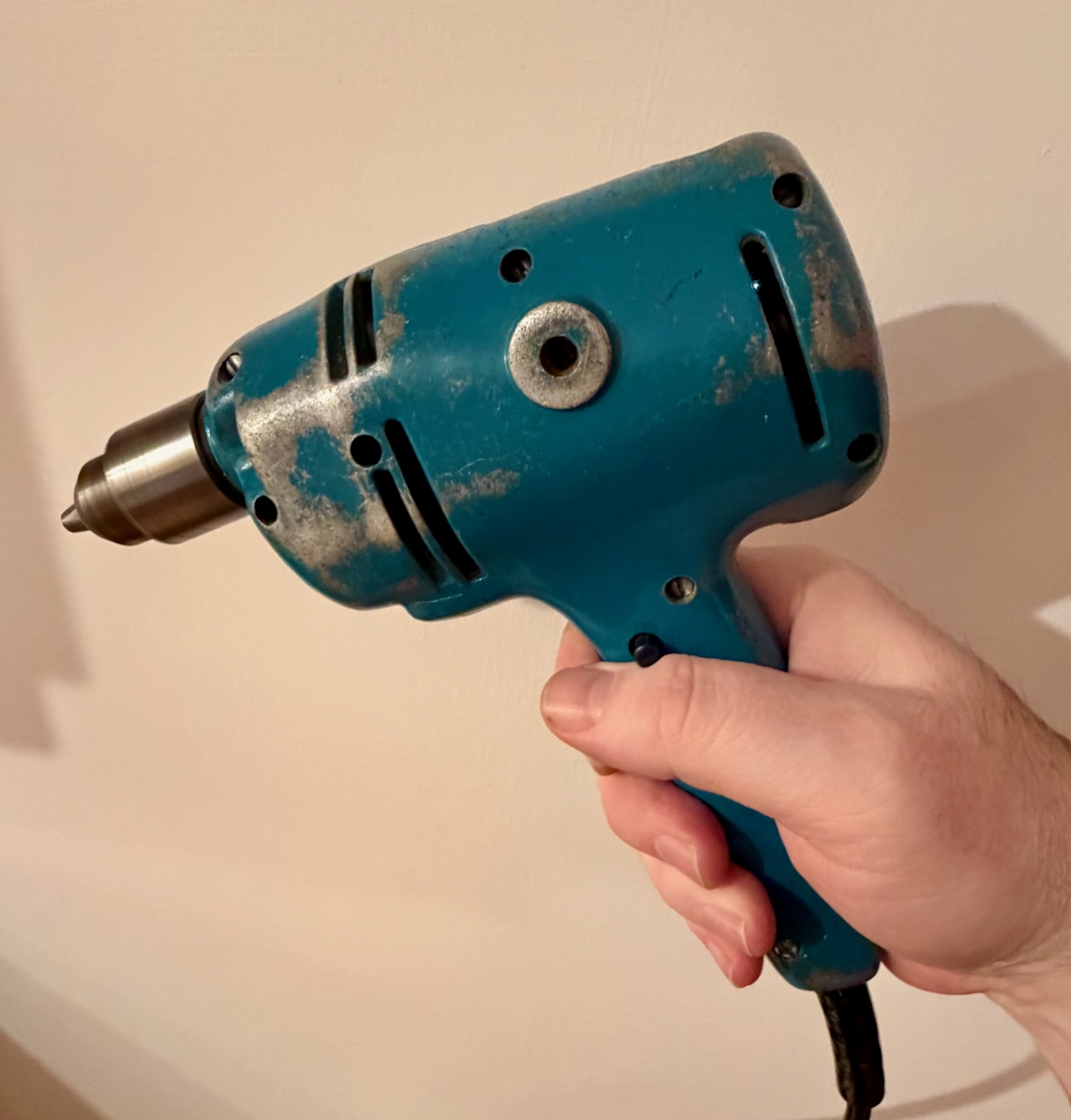
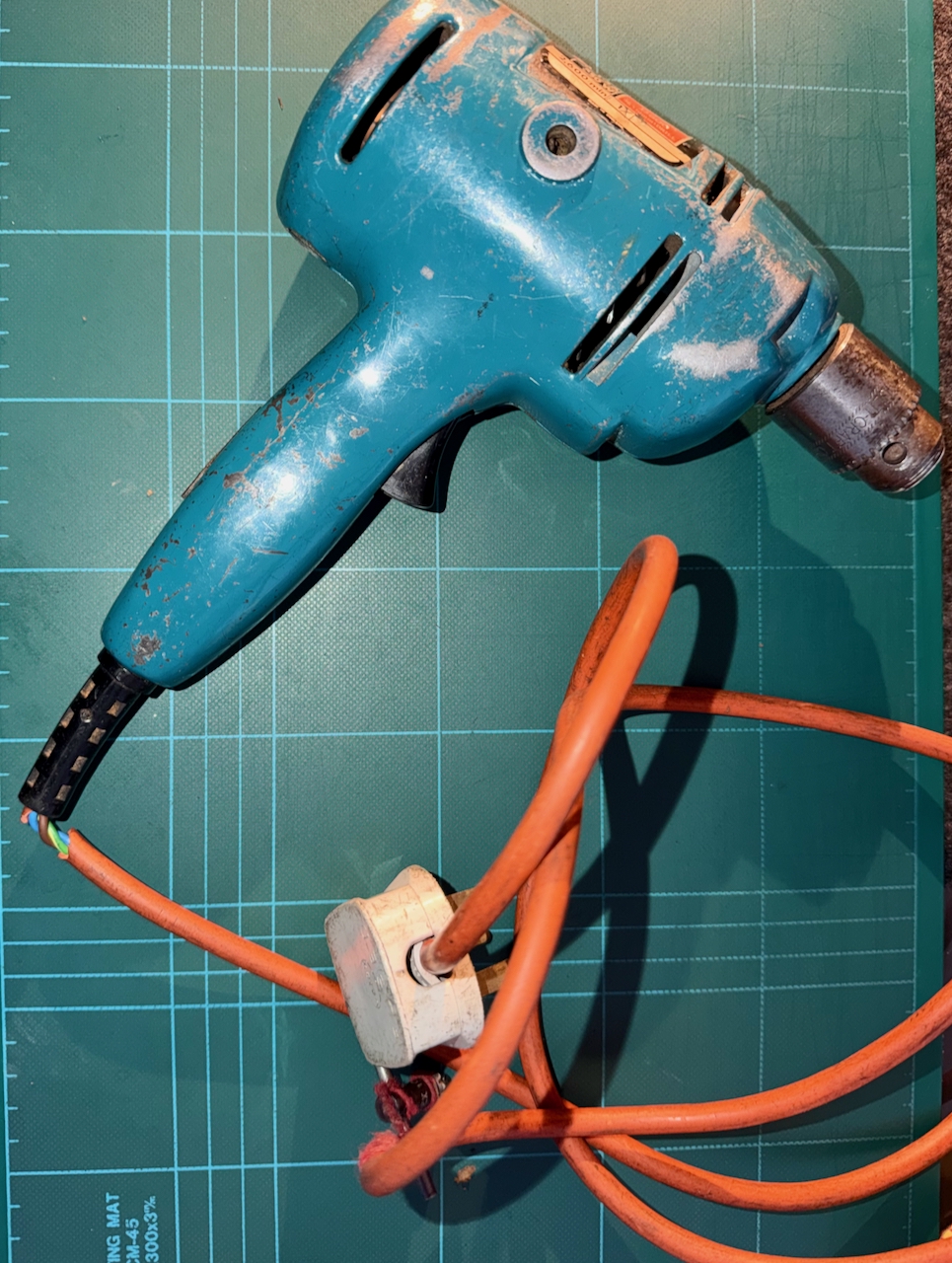
The Black and Decker Super D500 is a 1.5 amp 250W drill dating from the 1960’s. Lots of these must have been made as they seem readily available on eBay with prices from £13. I inherited this one from my father, and it hasn’t been used in many years. I recall as a child being the ‘gofer’ for him while he installed central heating, and re-wired houses. I have seen this drill through timber, concrete, brick (including Accrington brick – eventually) and metals – aluminium and steel.

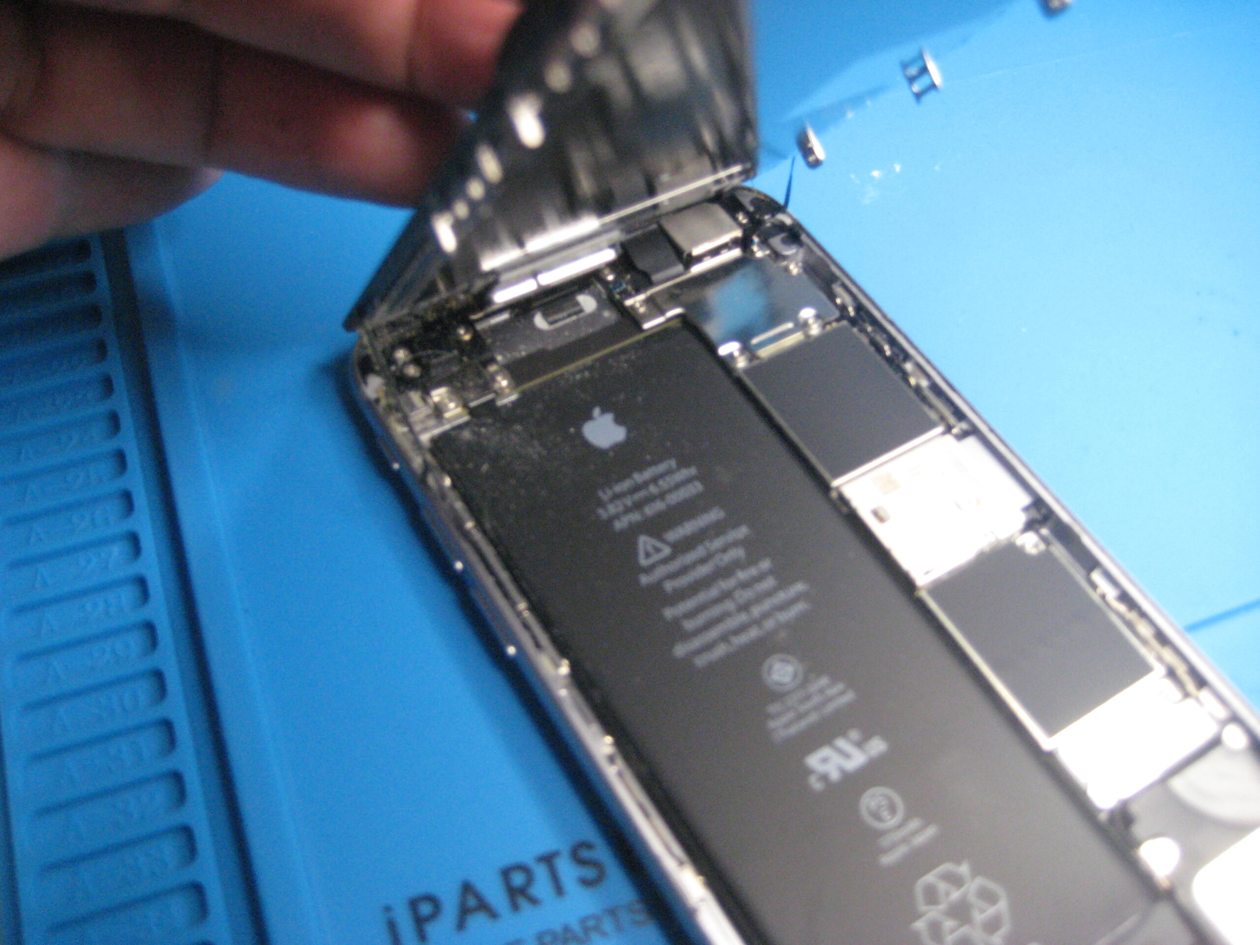
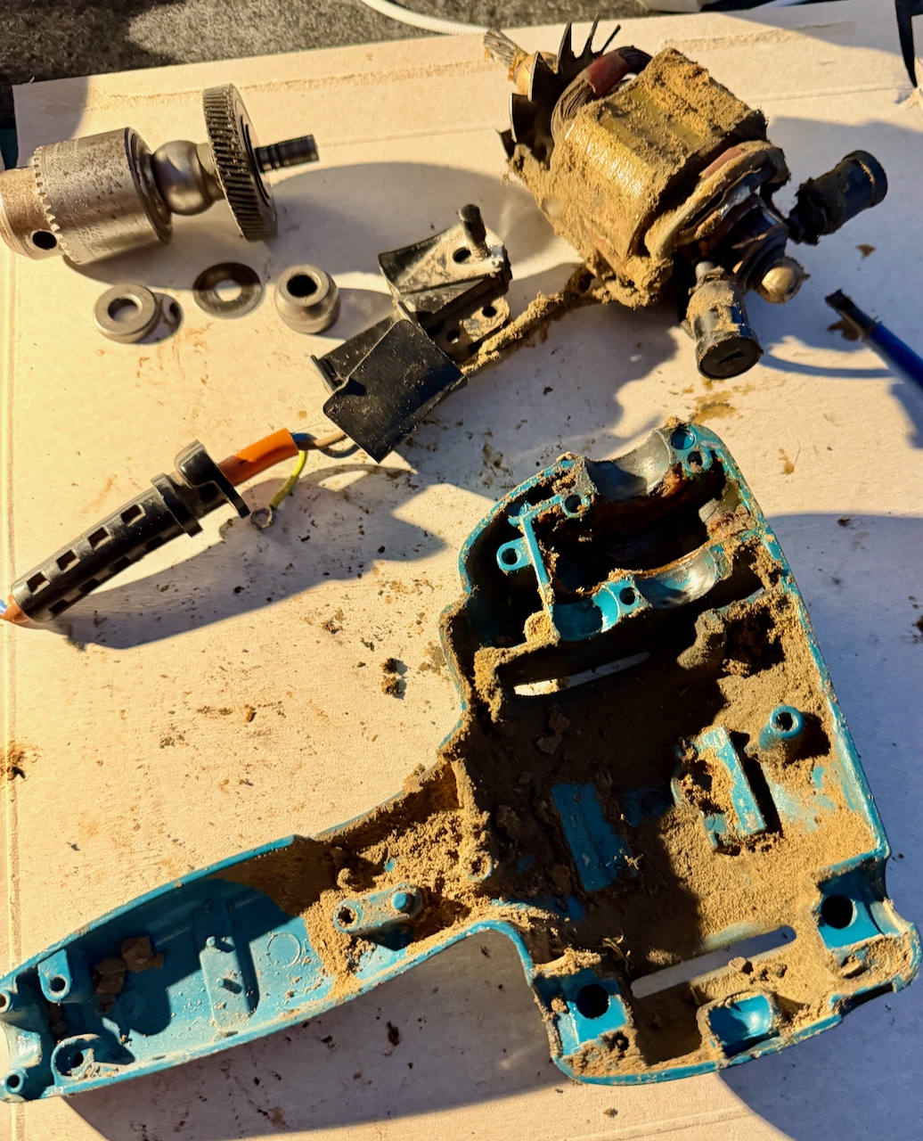
The orange outer insulator of the mains cable is starting to perish, and has broken as it exits the strain relief. I don’t believe it has ever been opened up since it left the factory.

Black and Decker Super D500 drill, with broken outer insulation of the mains power cable.
Black and Decker Super D500 – Broken mains cable

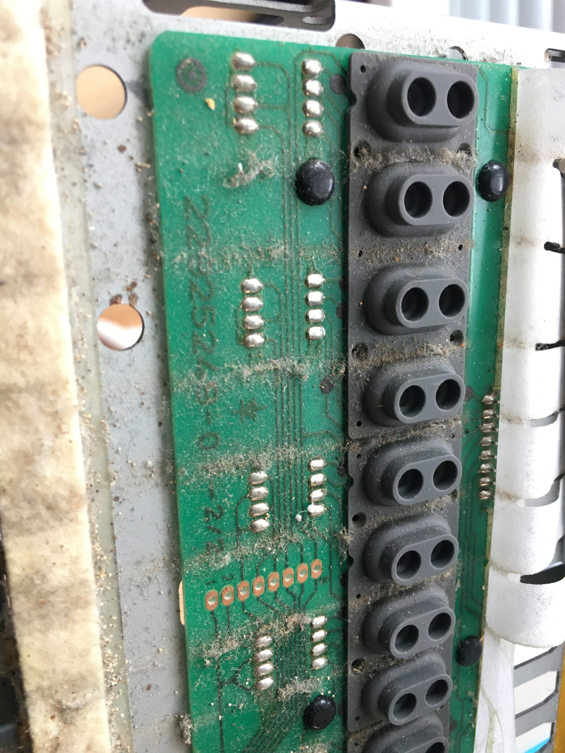
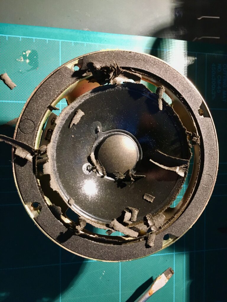
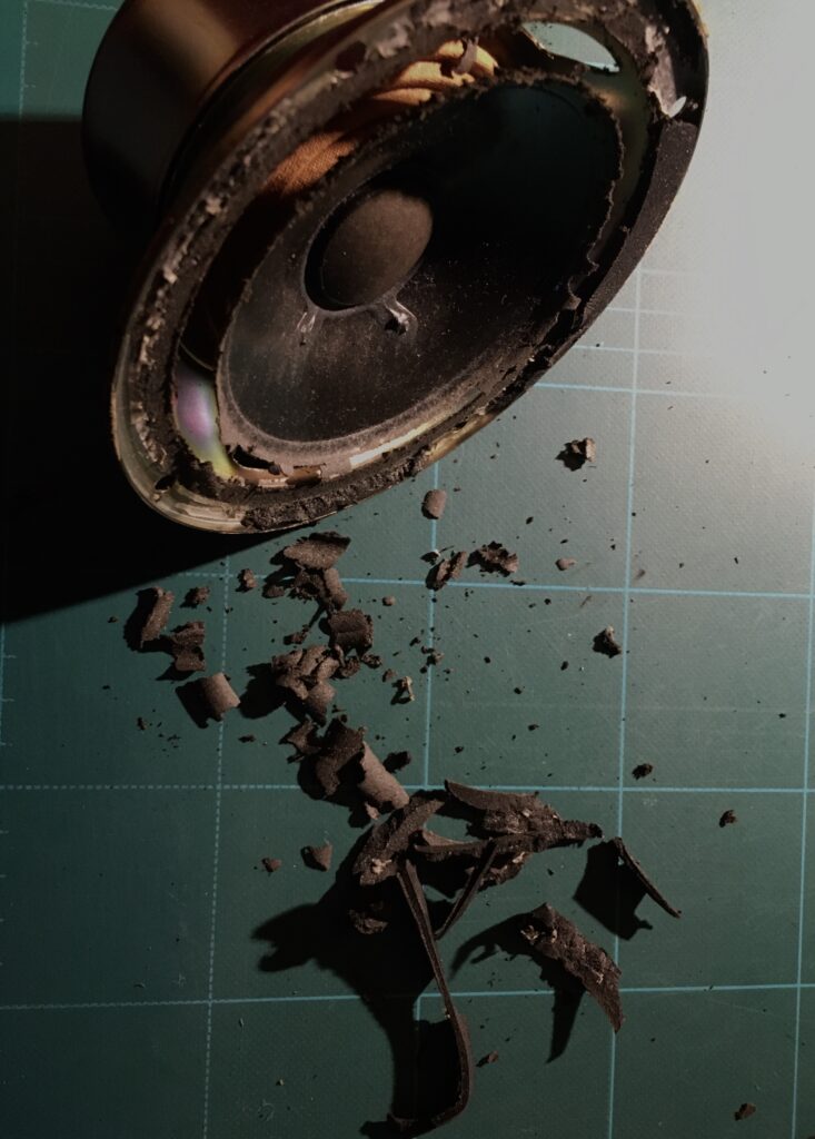
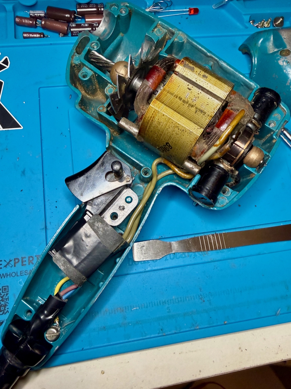
To get inside, the two halves are fixed together by 8 equal sized screws. As the drill is opened up, we can see that every internal surface is thickly coated with compacted dust of all the material types I mentioned earlier – particularly it seams, red brick. It fills the gear area, and motor, everywhere.

Black and Decker Super D500 drill. Cover removed, revealing inner chambers coated in dust from the materials drilled over the years.

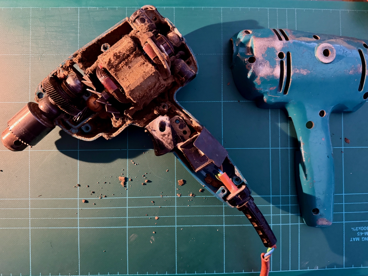
To ease things, I cut the mains cord, and removed the components from the back shell. They all simply lift out with no additional fixings.

Black and Decker Super D500 drill. Components lifted out.

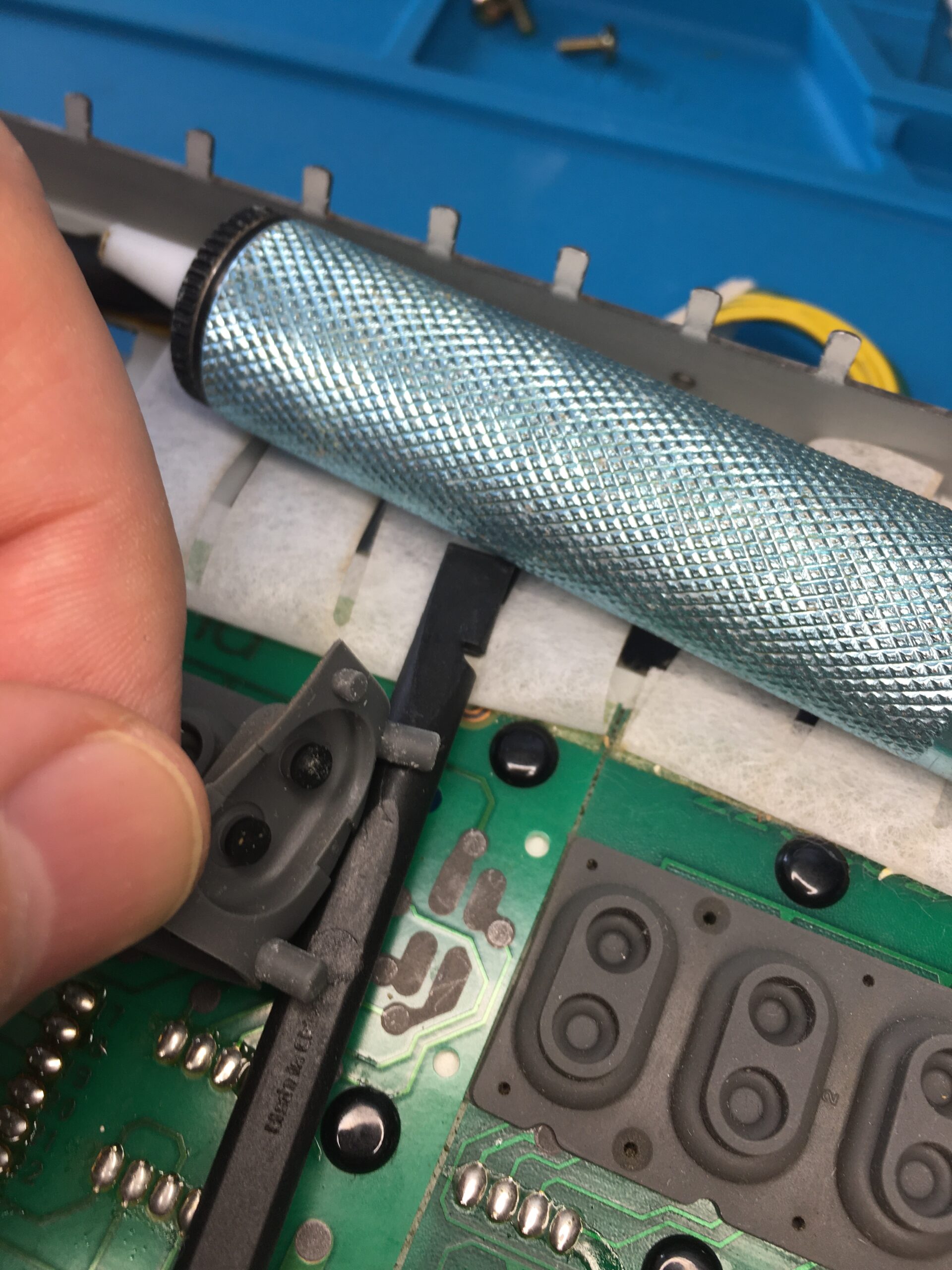
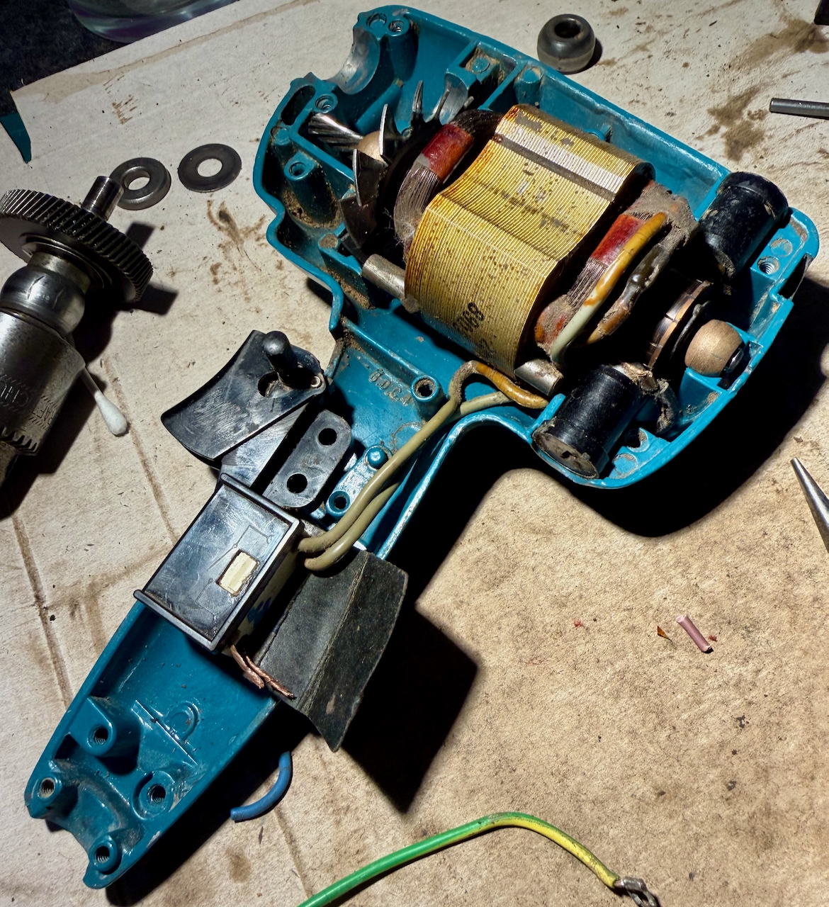
Then, first before dealing with the cable replacement, the clean up. A screwdriver to release the worst of it, then a good squirt of isopropyl alcohol to further clean the surfaces.

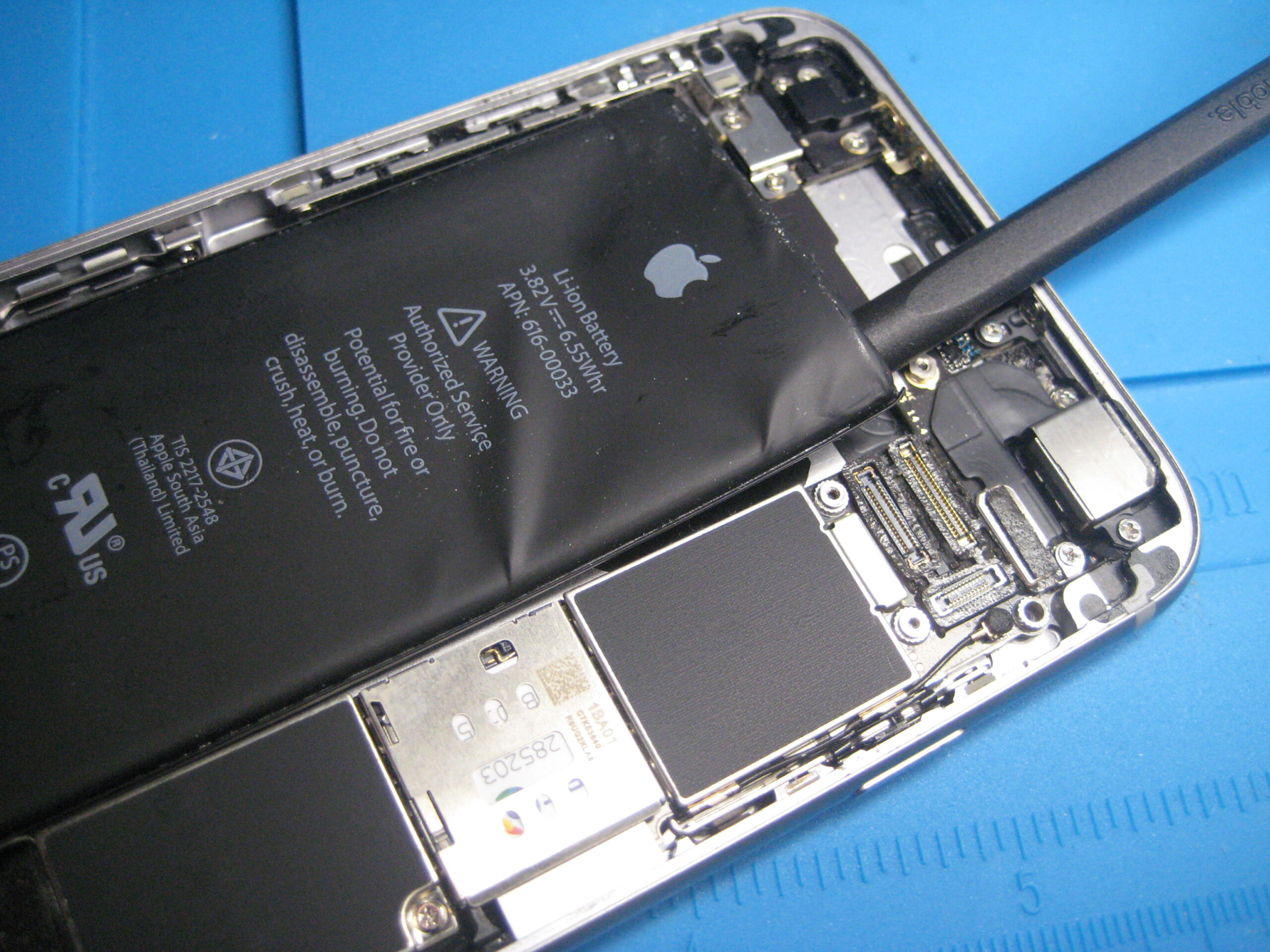
The compartment containing the gear from the motor shaft to the chuck shaft was full of old, sticky grease – mixed with the same dust. This was all scooped out and again further cleaned with isopropyl.

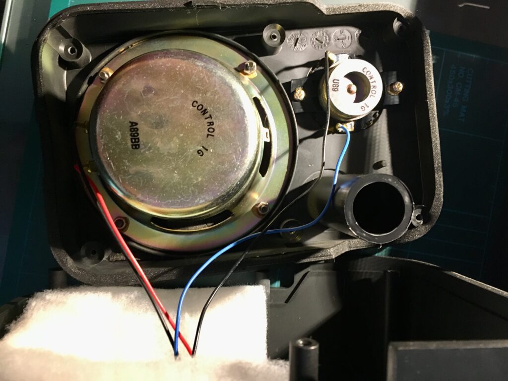
Taking care not to damage the wires, the dirt was cleaned from the motor, the brushes, the cooling blades and switch.

Black and Decker Super D500 drill. Internals roughly cleaned.

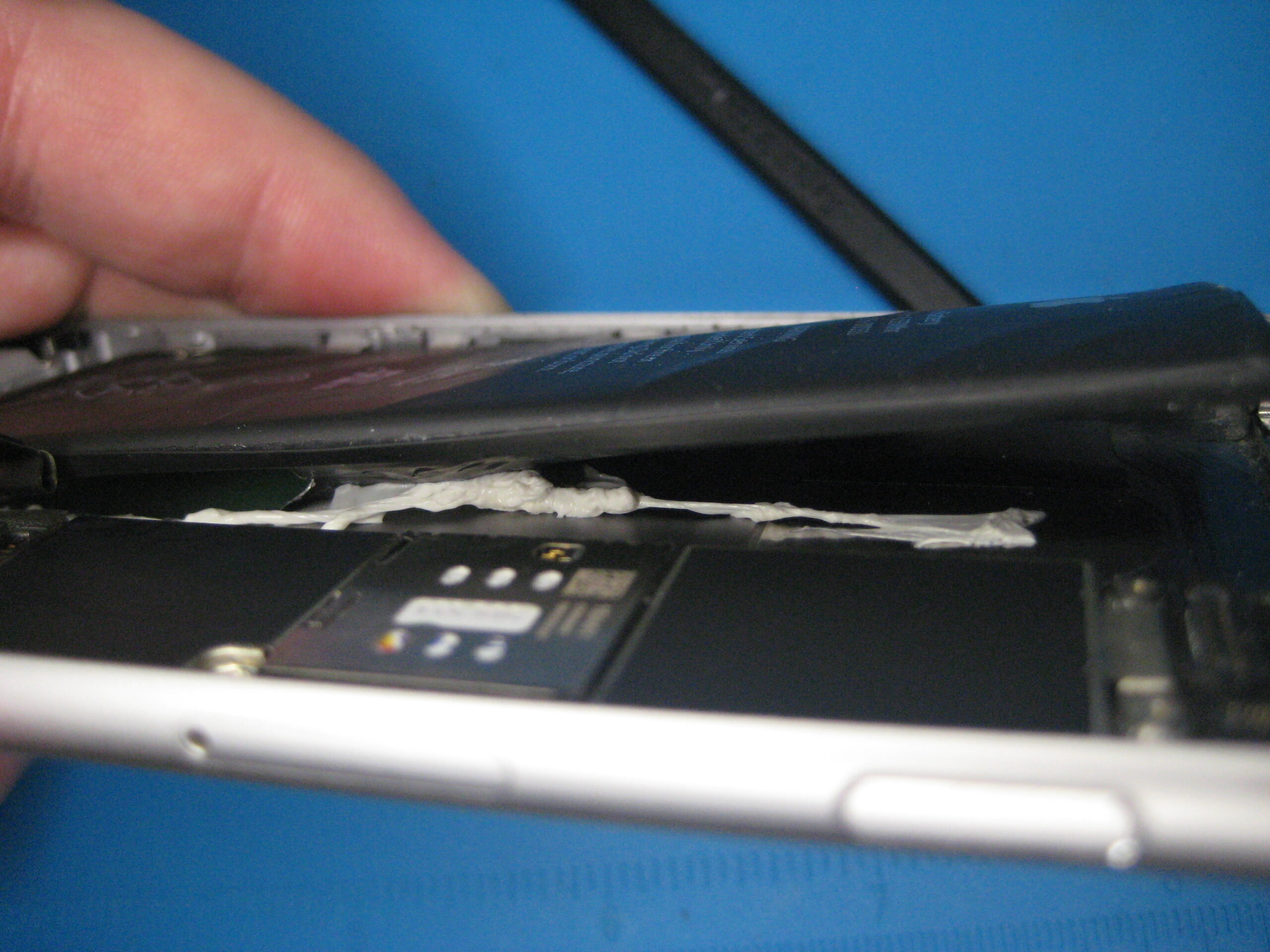
To re-use the strain relief meant removing the old cable. Very much easier said than done, as it felt very solidly stuck in there. First I cut it free from the other components, and pulled through each of the core wires, leaving only the orange sleeve. Since this was starting to perish, simply using long nose pliers pulled a bite out of the material, leaving the rest in place. I poked through the edge holes of the strain relief to try to separate the two materials. In what I think was a mistake, I cut through the thickest part of the relief, and eventually managed to pull the orange insulator free.

Removing the cable from the strain relief, first by removing the core wires, allowing the outer orange sleeve to be pushed away from its tight fitting to the black outer.

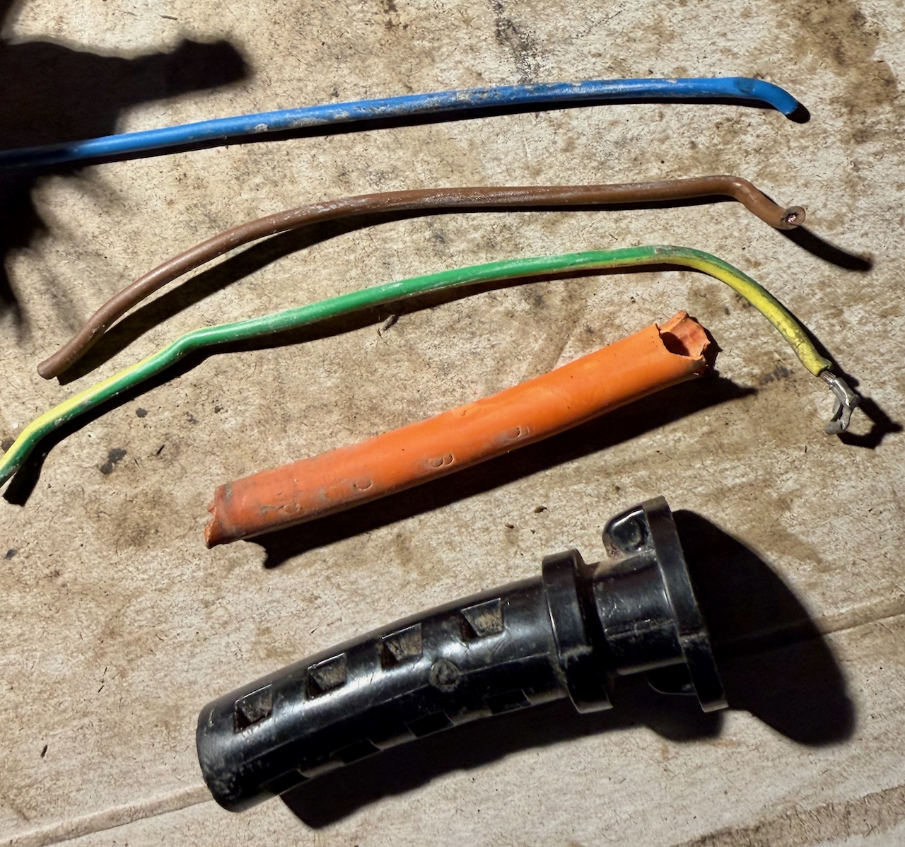
The new cable has a slightly smaller outside diameter than the original, and as we will see, it is important that the cable is gripped in-place by the strain relief. So, I gave it a few wraps of electrical tape inside the grip.

Connecting the new cable to switch RB1

RB1 switch with stubs of the old cable, and wires to the motor brushes.

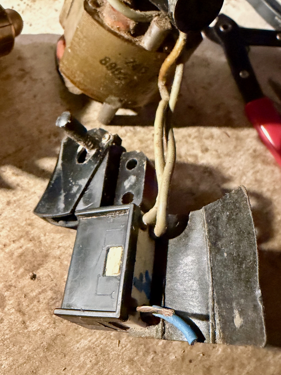
I found myself disassembling the switch entirely since I couldn’t see how the wires were screwed into the terminals. That’s because they are not – they just need pushing in. To get the old ones out, just push a small screwdriver alongside the old wire to free it from the grip. Then push in the new wires. I think it is better if the wires are twisted and tinned with solder.

The screw-less, push-in mechanism of the RB1 switch.

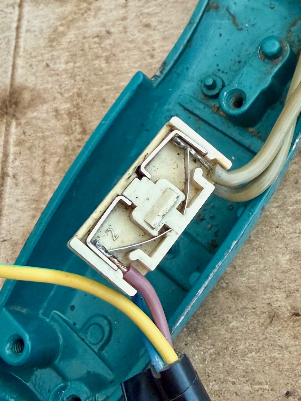
Warning if you decide to disassemble the switch. It contains springs and very small parts that can launch in many directions.

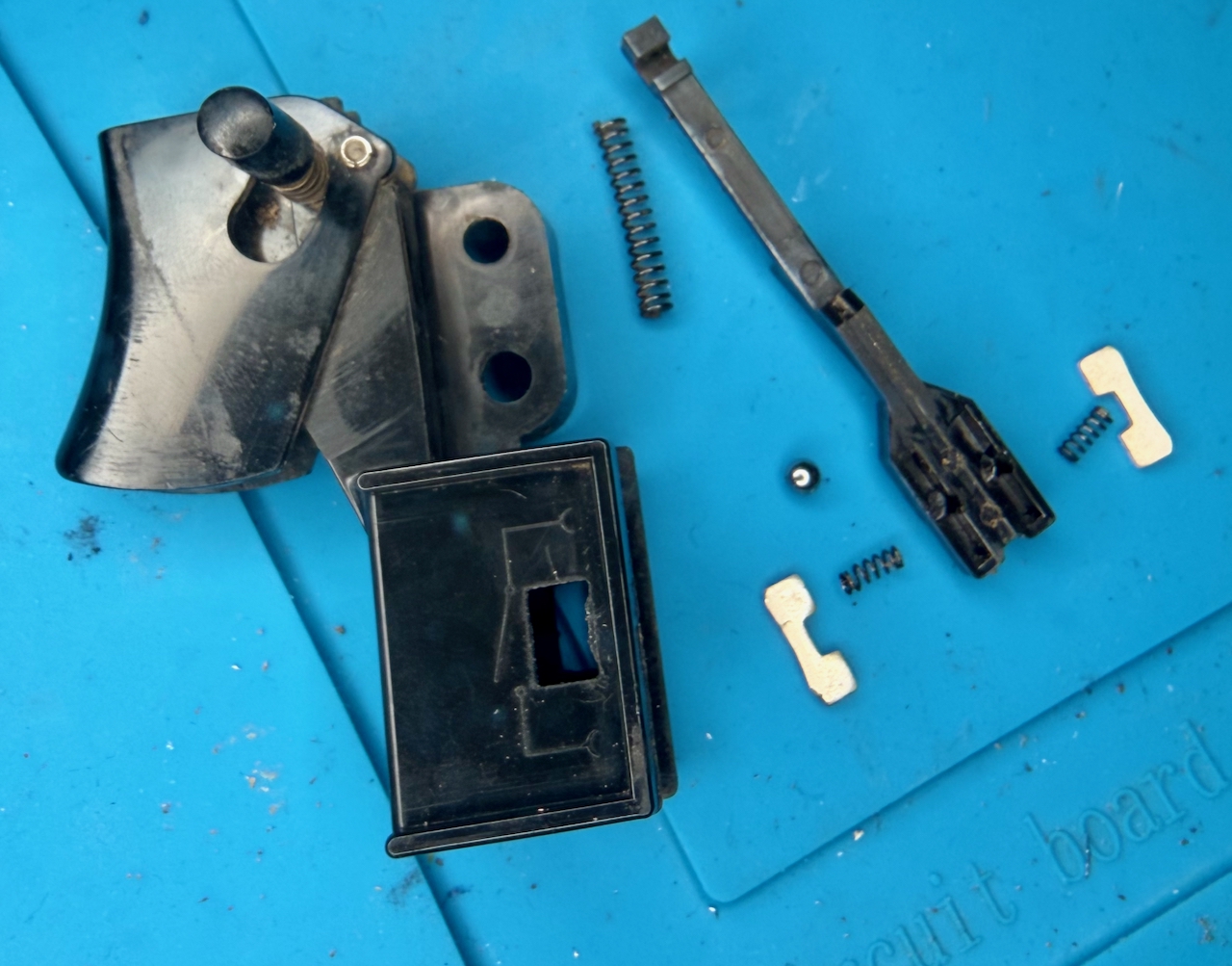
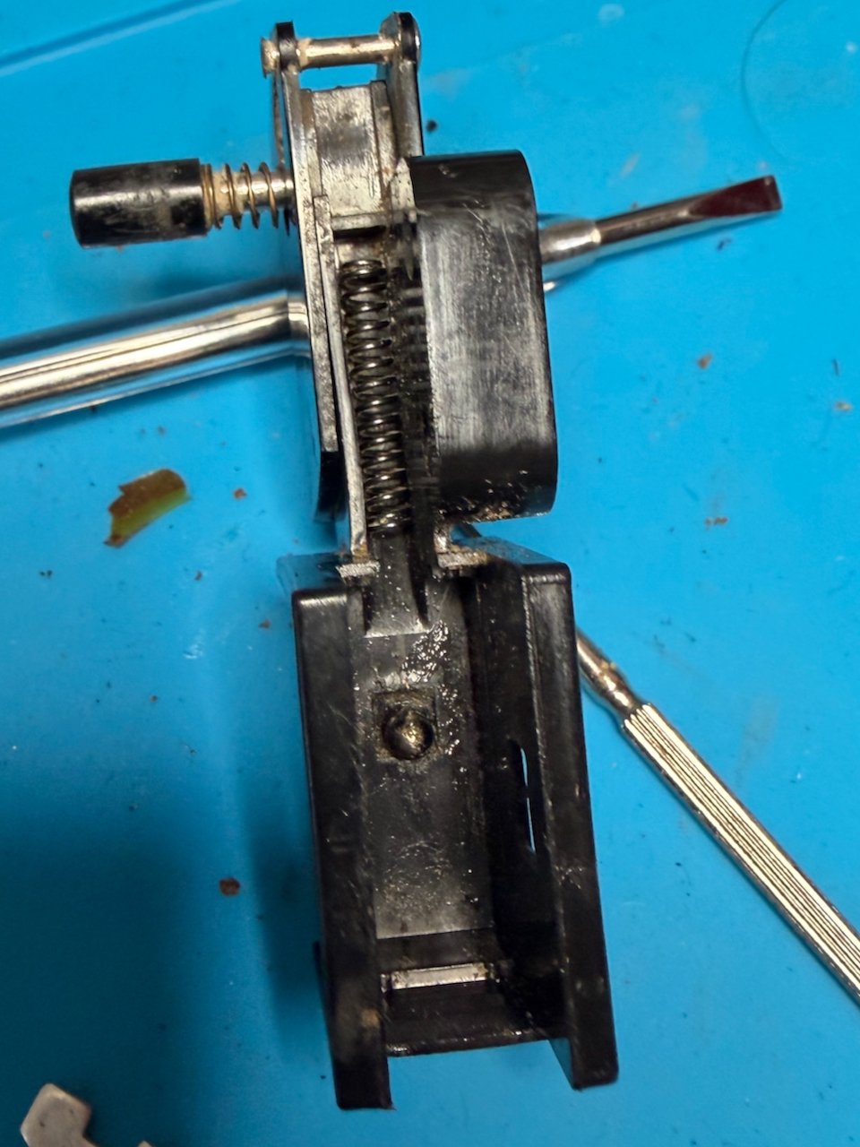
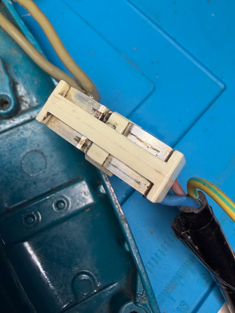
To separate the white connection block from the rest of the black switch, you can see that the white block has a lug each side. This does not move. To release the block, push a slim/small screwdriver between the outer shell and the block at the point of the lug. It is the outer black shell that must flex, not the inner white. Carefully pull out the white block, and be aware that the other parts are likely to fall or spring out.

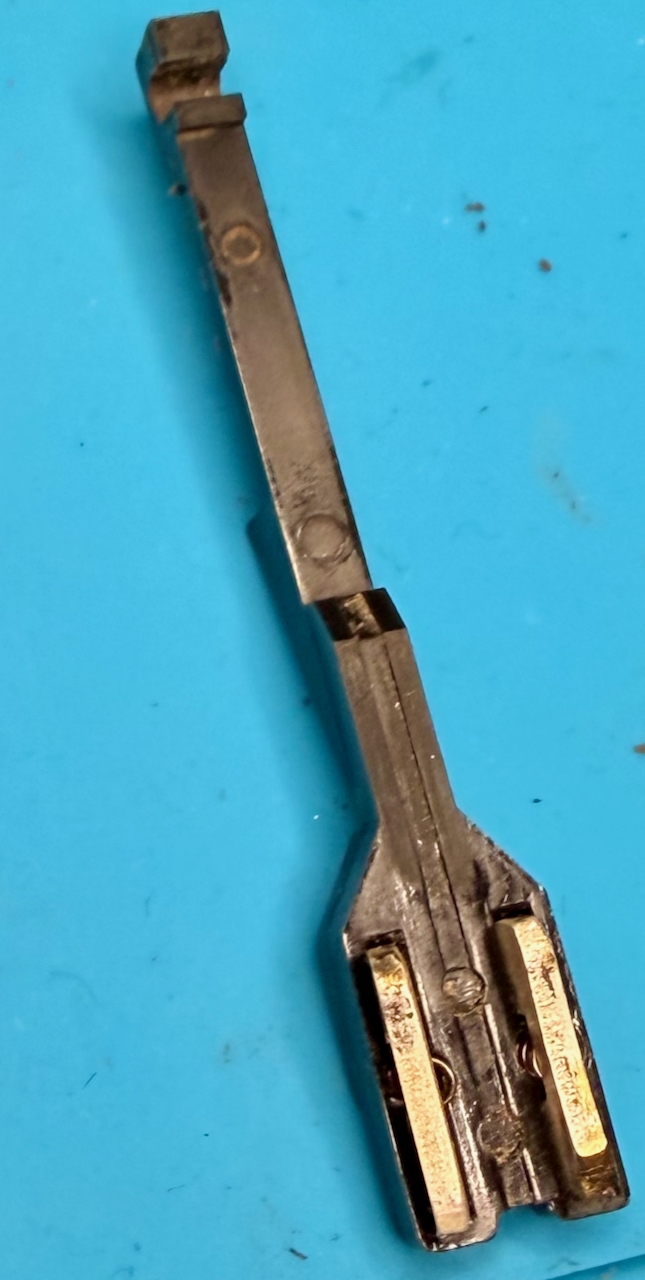
The black frame includes trigger and lock-on mechanism that I left in place, then the rest of the switch is made up of a sled with two spring-loaded contacts, that is pulled by the trigger to make the circuit. In my case I could see that one of the sled contacts was showing signs of wear possibly from arcing. On the reassemble I decided to make that the contact for the neutral rather than live.

Components of the RB1 switch: The frame, including trigger and hold button; a sled which the trigger pulls against a large spring, over a ball bearing, and presses through the two smaller sprints, the metal contacts.

After cleaning, to reassemble, my steps were:

  • Place the outer frame on its back and drop in the large spring, and the ball-bearing into the square recess
  • Hook the sled with the trigger in the off position, and lower into the assembly, it should align such that the hole with the spring is over the ball bearing. Hold the sled in position without letting the bearing fall out of position and roll around
  • Into the top side of the sled, drop in the two springs and carefully place the contacts
  • keeping the sled in position, slide in the white contact block, along with the insulation wrapper (in my case I forgot the wrapper and rather than disassemble again, I secured it with electrical tape
  • Once assembled, use a continuity meter to test the switch in open and closed positions
RB1 switch, outer frame on its back, with the large sprint and ball bearing in position.
RB1 switch sled, with contacts in-place, ready to be hooked into the switch frame over the large spring and ball bearing.
The white contact block clips into the black frame over the sled - and must be done such that the ball bearing remains captive in the recess underneath.

Reassembling the drill

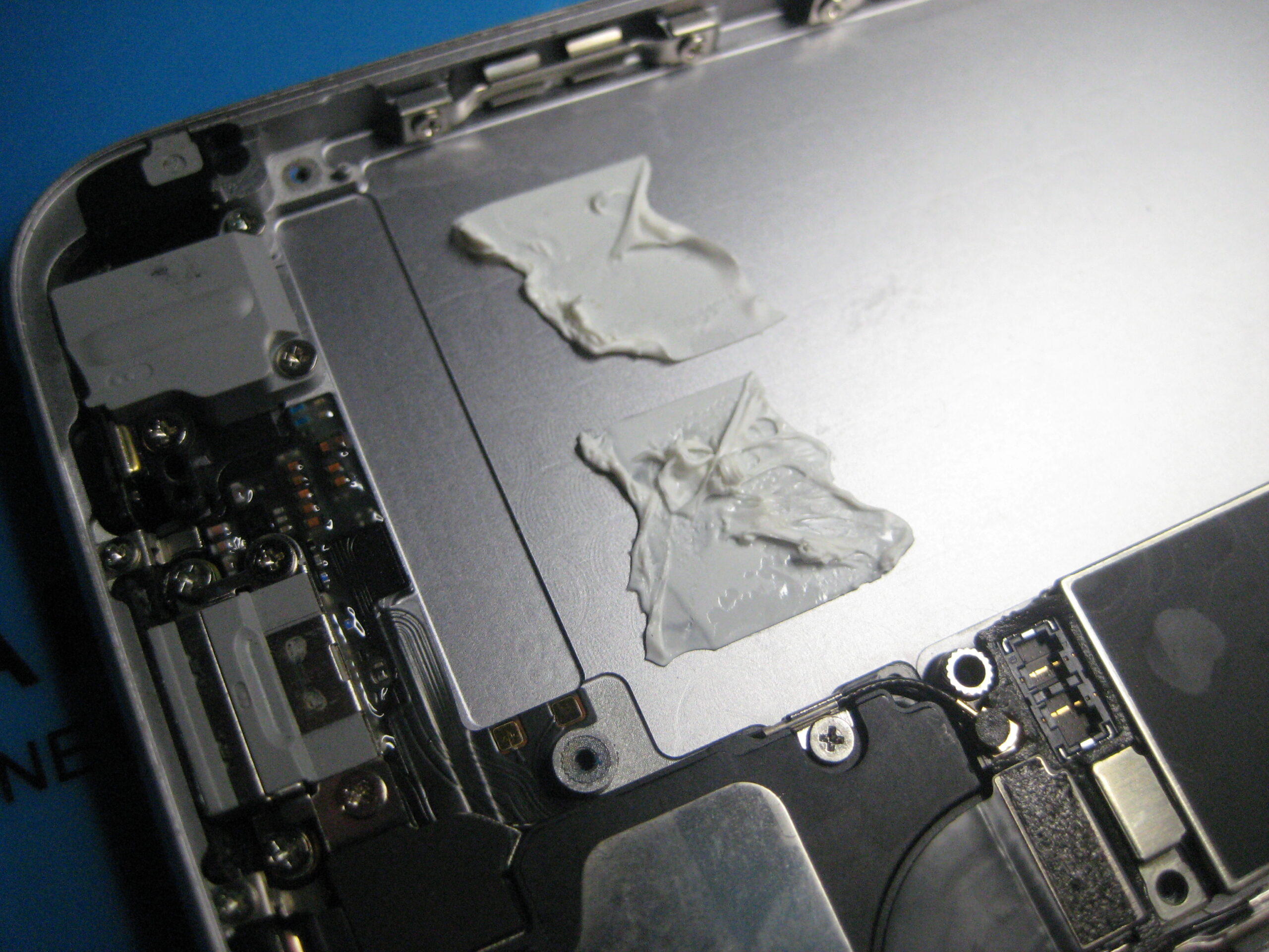
A few drops of 3 in 1 oil in the bearings and the motor and and place all the components into the back shell of the drill.

Reassembling the Super D500, showing the new cable connected, the earth connector secured.

Carefully secure the earth connection. There is a washer that I de-soldered from the old cable and soldered to the new before screwing to the metal shell.

Greasing the main gear - all teeth of the drill.

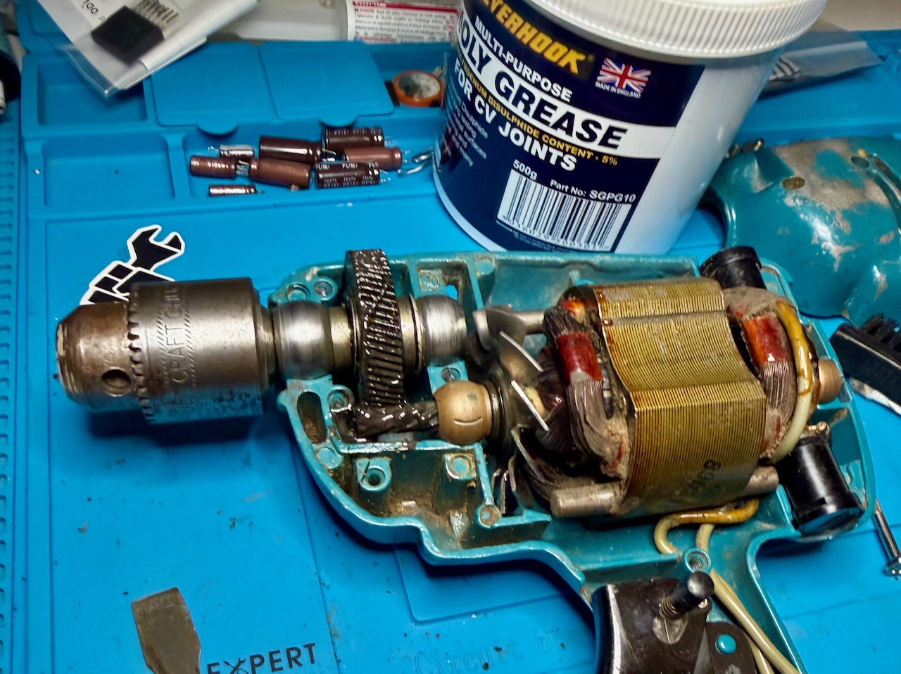
Grease the main gear. I used a moly grease that was much less viscous, and needed less in quantity than the original grease – although I don’t know how much of that was through being old and contaminated. (I think I only used about 1g of the 500g tub.) Carefully rotate by hand to distribute the grease heavenly between the gears. I am not sure if this is the best grease to use for the long term, but this drill will only have light use for the rest of its time with me.

Ensure the carbon brushes are properly positioned. Then close the front shell, securing with the 8 screws.

Be sure to test before plugging into power:

  • There is excellent continuity between the earth of the plug and all exposed metal of the drill. (The shell where the paint has worn down; the chuck, the screws
  • Check continuity between live and neutral, that is open (no continuity) with the trigger in the off position and closed (continuity) when the trigger is pulled
  • Check that there is no continuity between any of the metal parts and live or neutral for the switch in both positions

Plug in, it should work, sound, and smell a lot better than it did before!

Cleaned up Black and Decker Super D500 running smoothly

Posted by creacog, 0 comments

The Crucial BX500 SSD was a mistake in my case

A couple of weeks ago when I replaced the blown Crucial MX500 SSD system drive in my iMac 5K 2019, I made what I now think was a mistake in choosing the Crucial BX500. I had read that the MX500 that I had been using for years was end of life, and I assumed the cheaper BX500 might be its replacement. But far from it.

The warning signs were that in recovering the system, it took an exceptionally long time, and frequently displayed the prohibited icon. This, despite knowing the correct system was installed on the drive.

Prohibited icon

I consulted Claude.ai in search of insight beyond the advice in the Apple support article. It asked the model of the drive being used:

Claude: What type of SSD is installed?

Me: it is a crucial bx500 ssd aftermarket, replacing a prior aftermarket ssd that had failed following a problem with the power supply board

Claude: That explains a lot. The Crucial BX500 is a budget SATA SSD that’s known to have compatibility issues with Macs, particularly with the boot process. Combined with your iMac’s power supply history, there could be multiple factors at play.

Claude: The BX500 issues with Macs:

  • Often has NVRAM/boot detection problems
  • The prohibited symbol cycle you’re seeing is a common complaint
  • Eventually boots but takes multiple attempts
  • Not officially Mac-compatible

Since at the time the only symptom I was aware of was the prohibited icon appearing on a cold boot, and not really wanting to spend more on this repair, I hoped I’d be ok only sleeping the system as a rule. After all, the restore had successfully written around 800Gb of data.

Unfortunately over the next weeks, more of the reported symptoms started to appear. Spinning beachballs, system slow-downs etc. These seem to happen when lots of small files are being written especially by browser activity and time machine back-up activity. One two occasions the system eventually crashed. Prior to using this drive it never crashed.

Claude suggested, after I told it MX500 was being phased out:

  • Samsung 870 EVO (widely recommended for Macs)
  • OWC Mercury Extreme Pro (Mac-specific)
  • Western Digital Blue SA510

I asked Claude for a comparison between the BX500 and the WD Blue 510

*** Claude start ***

Technology & Architecture:

  • BX500: Uses QLC (quad-level cell) NAND technology Best Buy, which stores 4 bits per cell, and lacks DRAM cache (uses Silicon Motion SM2258XT DRAMless controller) SSD TesterTechPowerUp
  • SA510: Uses Western Digital’s own 3D TLC NAND technology B&H Photo Video (3 bits per cell) with SLC caching that temporarily boosts write speeds B&H Photo Video

Performance:

Both drives advertise similar peak speeds:

However, sustained write performance differs dramatically:

  • BX500: After writing 25 GB, write speeds drop to around 100 MB/s TechPowerUp. In the 2TB model, after approximately 184 GB, write performance is throttled with average write speeds of 151 MB/s Best Buy. After filling 60% of volume, speeds can decrease to a very low 60 MB/s Western Digital
  • SA510: After approximately 54 GB, the pSLC-Cache was full with average write speed of 287 MB/s Product Chart – significantly better than the BX500’s post-cache performance

Reliability & Endurance:

  • BX500: Among the lowest endurance ratings on the market, starting at 40 TBW and spanning up to 120 TBW SSD Tester
  • SA510: 400 TBW endurance rating with a five-year warranty B&H Photo Video – over 3x better than BX500

Mac Compatibility:

  • BX500: Known issues with Macs, including write speeds hovering around 10-15 MB/s on iMacs even after fresh OS installations Tech Atlantix
  • SA510: Better general compatibility, fewer reported Mac-specific issues

Bottom Line

The WD Blue SA510 is the superior drive with better sustained write performance (287 MB/s vs 100-150 MB/s post-cache), much higher endurance (400 TBW vs 120 TBW), and better Mac compatibility. The BX500’s QLC NAND and DRAMless design make it struggle with sustained writes – exactly what you’re experiencing with your migration and speed tests.

For a 2TB upgrade in your 2019 iMac, the SA510 would be a significant improvement over your BX500.

*** Claude end ***

WD Blue SA510 SATA SSD 2TB

I was persuaded, and got hold of the WD Blue SA510. First using an external USB 3 enclosure, I repeated the system recovery and time machine recovery to that drive – taking at least 2 hours less time, and not seeing the prohibited icon once. The Black Magic Disk Speed Test showed consistent read and write of around 350Mb/second. With a few days operation and no slow-downs, spinning beach balls, or prohibited icons on a cold boot, I moved the drive to the internal SATA without issue, and there seeing writing consistently at 450Mb/s and read 483Mb/s. This time I have the confidence to re-stick the screen.

I do have a BX500 1TB in my PS4, and it has been working perfectly well there without any noticeable issue. Maybe this one will be ok as an archive drive – but not for anything requiring lots of sustained writes.

Posted by creacog

iMac 5K 2019 repair – Blown power supply board

TLDR

When I upgraded the fusion drive to SSD, I opted to include the OWC in-line Digital Thermal Sensor. That sensor was the root cause of the repair needed here, and ironically, I don’t think it was ever needed in this model iMac.

Detail

A couple of years ago, I removed the 1Tb fusion HDD from my iMac 2019, to replace with a 2Tb Crucial MX500 SSD. There was some confusion at the time as to whether the iMac would depend on the drive having a thermal sensor, without which it may run the fan at full speed always. Therefore I got hold of the OWC bundle including Digital Thermal Sensor and Glue strips and installed as written up here.

After just over 2 years of faultless operation there was a loud ‘crack’ noise from behind the screen and the iMac was instantly dead – with no means of powering it up. I was pretty convinced that the power supply board was the affected component and ordered a replacement (2nd hand) via ebay, and avoided opening up the iMac until that had arrived.

I then started work cutting the screen glue with the old iFixit cutter. It felt much more difficult than the original glue a couple of years ago, and at some point I managed to break the cutter wheel.

iFixIt cutting wheel - broken blade
iFixIt cutting wheel – broken blade

At which point I ordered a new cutter with spare blades via Amazon. I then made a crutial mistake… I attempted to continue working around the screen but using a pick tool. I should have just been patient and waited for the next day delivery, as the pick tool caused extra stress on the screen resulting in a chip of glass breaking free and some hairline cracks. Fortunately the worst of it is in the black bevel are, and I have simply covered with black electrical tape.

With the replacement blades the next day, I was able to remove the screen. At this point the root cause of the problem was immediately apparent. As you can see from the photo of my original work, the OWC sensor is stuck to the SSD.

Replacement drive in its mounting kit with its inline temperature sensor

With the screen removed, we can see that the sensor is nolonger stuck to the SSD, and has dropped, with the wires just long enough for the sensor to land on the power supply board. Closer inspection shows soot on the sensor board and missing components, and against one of the transformers of the power supply. The back of the sensor had lost all stick – the glue has completely denatured.

Inside iMac 5K 2019 showing the OWC inline thermal sensor unstuck from the SSD.
Close up of the OWC in-line digital thermal sensor, showing scorch marks and damaged components
Damaged OWC in-line digital thermal sensor
Close up of the visual damage to the power supply board.
Damaged power supply board, close up

I did have some worry about the power supply board that I had obtained via eBay – it was from an iMac 5K 2020, and while it looked the same size, its components were in a different layout. It does turn out that the board works well in this iMac.

The different component layouts of power supplies.

However, once installed, it was apparent that the SSD was no-longer functioning. So the next step, I ordered a Crucial 2Tb BX500. This turns out to be a potential mistake. On a cold boot, the Mac shows the prohibited icon for a while. This eventually clears, but the drive performance, particularly in the time machine restore is very poor.

New BX500 SSD in place, without any thermal sensor this time

In consultation with Claude.ai, the suggestion is that the BX500 is a budget drive and has some Mac compatibility issues. However following a few weeks basic operation which only involves creating and editing a few lightweight documents and online streaming, I have not hit any noticable issues – other than on a cold boot and that ‘prohibited’ icon.

The fan has been running normally, therefore I do not believe the thermal sensor was actually necessary in the first place, and my belt and braces approach has turned out to increase rather than decrease risk on this occasion.

If you decide to install the sensor (or already have) i recommend using cable ties and routing the sensor wires such that when it comes unstuck, it cannot fall into the power supply, or touch any other metal component.

Posted by creacog, 0 comments

Macintosh LC – Restoration plan

So, nearly a year passed since finding leaky capacitors inside my old LC. Finally getting around to sorting it out. The plan:

  1. Don’t power up until leaking capacitors have been replaced and the power supply checked
  2. Get replacement capacitors for the power supply
    • This should be easy – replacing like with like – but a decision to be made is whether to replace them irrespective of testing – on the basis that they are around 34 years old
  3. Get replacement capacitors for the logic board
  4. Get a Blue SCSI II card, with wifi and internal mounting
    • Opted for an assembled version – reducing the risk of my bad soldering affecting the main board.

I had put a larger hard disk in the Mac LC than the original 40Mb one. Unsure what size it is from the labelling but I am guessing it was probably 512Mb as they were pretty expensive at the time. The plan with the Blue SCSI is to copy all the data from the hard disk at the first opportunity after power-up, and replacing with the Blue SCSI for then onwards. Additionally, the old CD-ROMs I had for the LC will be copied to disk images on the Blue SCSI SD card.

For my research I watched a number of YouTube videos. In particular:

Order in to Mouser, and mistake number 1. On Mouser, they use the nice large yellow package size for the tantalum caps as you see on the videos above – but this is a generic image they use for all Tantalums and I had not taken into account the various package sizes. To be fair to me, the experts in the videos above don’t mention the package sizes. I ended up with some of these…

Tantalum Caps strip 10µF 16V

At 3mm, these were smaller than I expected, and gave pause for thought. I then watched this video which takes a different view on using tantalum caps. In short, Tantalum tends to fail by short circuiting with flames. Additionally, it is recommended to use a larger derating to minimise the likelihood of a fail. So I either need to replace these with ones derated further from 16V to around 25V, or use an alternative type: tantalum polymer caps, which do not burn when they fail and should be ok on the original derating.

In short, I have ordered tantalum polymer cap replacements for the main board, and sticking with electrolytic for the power supply.

Posted by creacog, 0 comments

iPhone 6s Glass Replaced

My iPhone 6s now good for a few more years before adding to the e-waste pile thanks to a replacement screen from iFixit.

So, it took me more than twice the time the article suggests, but I was going very carefully – and had a load of trouble fiddling with the screen connector. Other than that, all went smoothly, and the new screen appears slightly more rich in colour and somehow feels faster in response.

The official guide is here: https://www.ifixit.com/Device/iPhone_6s

How it went for me…

IFixit iPhone 6s tools and new part, nicely packaged - outer box
IFixit iPhone 6s tools and new part, nicely packaged - package contents
Broken screen before repair

I had been surprised how well the old screen continued to perform, with parts of it held in place by scotch tape, and that the finger print recognition continued to work through the tape.

I had turned on the on-screen home button just in case.

Although the really smashed area was around the home button, cracks extended in long arcs across the whole screen.

To get purchase on the screen with the sucker, I used a wide strip of packing tape. Although with some heating from a hair dryer, the glue strips seem to have melted easy enough.

Opening iPhone 6s, broken screen, sucker with packing tape and a pick after hot air

Vital step was to disconnect battery and not have it any way connected while disconnecting or connection the screen ribbons. Prior to the repair, charge had been reduced to less than 10%.

iPhone 6s Disconnected battery

A phone of two halfs. We need to keep the home button from the old screen, but the new one already has a front facing camera, so no need to mess about with that.

Two halves of iPhone 6 separated

Transfer the home button assembly to the new screen, and clean the back half of the phone of all the glue – transferring the new glue template.

Removing the home button assembly from the old iPhone 6s screen

Fresh glue in place, screen re-connected. Quick battery on test of the screen before closing and gluing back together.

iPhone 6s, reconnected, but open - for a test before sealing

Sealed and back in action

iPhone 6s, resealed, power off
iPhone 6s, new screen reading about the old screen
Posted by creacog, 0 comments

Macintosh LC – Leak check

My old Mac LC has a lot of sentimental value. My first Mac. The result of a major saving up exercise. Bought primarily for the final year of my Computer Science degree. I squeezed quite a long life out of it, with a DayStar accelerator card that I bought out in the States while attending the MacWorld Expo 1993 (and there is a story to that) but it has been in its original box for over 24 years.

I fully intend getting this machine going again, probably using a BlueSCSI or similar. But I had seen from the many retro-computing YouTubers varying levels of capacitor and battery leakage. So today was a quick inspection to see if it is similarly affected.

On first inspection, the battery looks ok. No sign of leakage, but quite flat, only able to deliver 41 mV as opposed to the 3.6V. If that’s a date code on the battery 11/89, I guess expecting any change remaining after 35 years was optimistic.

At a glance, there didn’t seem to be much problem near the caps. Although on closer inspection, it is clear that some of the component solder joints are matt with a green tinge – so, not so good. For now, I cleaned as best I can with isopropyl alcohol. The cotton swabs turning a horrible greenish colour kind of confirms the leakage. The board however does look in decent condition with the traces looking good.

Recapping is going to be vital I think before applying power back to the machine.

Additionally, it was also pretty sad to see how brown the casing had turned. It has spent a few years in a brightly sun-lit room before being boxed up, and is no-longer the nice light grey I remember. I’ll have to consider retro-brighting – but for me, this particular unit is a one-off. I don’t want to mess it up and I live in a flat – with no outdoor area for the sun part of the process, it is going to be a challenge.

Posted by creacog, 0 comments

Roland Alpha Juno 2 repair time

TLDR: I need to make the following repairs to my Roland Alpha Juno 2

  • Fix the touch sensitivity of one of the keys
  • Fix the non-sounding keys
  • Replace the back light
  • Replace the battery
  • Give it a good clean, inside and out

Using online articles and YouTube videos, I get into the repairs after sharing my history with this synth.

I saved up and bought it new in around 1986. I originally had a couple of small Casio keyboards PT-50 and MT-400V, and got my hands on a Roland SH-101 but wanted to step up to a polyphonic synth.

I was on a year out after my A-Levels, and earning, so a bus ride to into Manchester to hand over some cash (around £700 if i recall) and pick up my new Roland Alpha Juno 2. I’d never call myself a musician – I just enjoyed playing with the synthesis and trying to emulate the sounds of my favourite artists and bands of that time: Jean Michelle Jarre, Gary Numan, Ultravox, Human League, OMD and Pink Floyd.

I have always liked this synth and the feel of its semi-weighted keyboard and it seems to have lately found some popularity as a retro synth used by artists such as Kebu.

The synth (and home made amp) came with, as I left home in 1988 to study for my Computer Science degree. It survived the halls of residence and two student houses despite a near constant fear of being burgled.

In my first year however, it started behaving erratically and needed a repair. Rock city in Middlesborough did the repair job, which included replacement of the memory backup battery and some fuses. It hadn’t been again since. I’m amazed that the patches programmed over 30 years ago remain intact. Having owned it from new, I attach a lot of sentimental value to this synth and I don’t want to ruin it while I attempt to repair it.

I was able to find the reference materials on manualslib. Additionally I searched and found a number of repair videos on YouTube:

Saving the patches

Since I am going to change the battery, I need to dave the patch memory. To do that I used SysEx library on my Mac, and on the Juno, pressed simultaneously:

  • Data transfer
  • WRITE
  • Bulk

This sent 16 messages (4.2 Kb) to SysEx Library, which seems tiny by todays standards, but represents the 64 user defined patches.

Sysex of my Juno 2 user patches

Bad keys

First I marked the affected keys with tape:

  • The bottom C key, always plays 20% louder than other keys
  • The top D key, always plays 100% velocity, no matter how softly played
  • The middle G key does not sound
Alpha Juno 2 - Faulty keys labelled

Once inside, removing the keybed is a delicate and fiddly process – since the main board is slotted into the keybed. A rough hand could easily cause damage to that board. Ever careful to take photos of all the connectors in place, to provide reference for reassembly.

Alpha Juno 2, Opened
The main board sitting under, and slotted into the keybed.

The approach I took unscrew the board from the frame and slide it out, disconnecting the many connectors. Once the main board was free, I unscrewed the keybed from outside of the case and worked on it separately, away from the delicate electronics.

To get to the contacts we need to first remove the keys to which there are 3 stages:

  1. Remove the springs, keeping the shorter springs of the black keys separate from the larger springs for the white keys
  2. Underneath the keys, unstick and put aside the ‘Key Stoppers’ (clear plastic strips) that prevent the keys from slipping forwards.
  3. The keys will now pull forward and can be removed

Despite a good portion of its time boxed, thirty-odd years of dirt had certainly built up. With all the keys removed, all the dirt was brushed and vacuumed away, then the graphite pads of the affected keys cleaned. Removing the glue used to stick the key stoppers was the most time consuming effort.

All the keys went into a bucket of mildly soapy (washing up liquid) water for gentle but thorough cleaning before reassembly.

Backlight

In many of the restoration videos the LCD display is replaced with an LED display. I opted for replacing the electroluminescent strip with a new one. I managed to do this simply by desoldering the two connectors and slipping the strip out – without detaching the display from the frame.

Battery replacement

I opted to replace the soldered battery with a battery holder and standard CR3032. It was impressive that after over thirty years powering the memory for the user patches, the battery still held a good charge. Despite no liquid leakage, there was a white powdery coating building up on the battery.

Aftertouch

The remaining issue is that I have lost aftertouch. On testing the resistance of the aftertouch strip, I can see it changing with pressure. I hadn’t tested it before the disassembly, so this might have been an issue already rather than something I introduced. I may need to change the resistance range, but I haven’t yet worked out what that should be. One for the next project.

Conclusion

Aftertouch aside, I now have a clean, working Roland Alpha Juno 2. It makes a great MIDI controller for working with any DAW. But in some ways that is a waste for what is actually a decent synth from the late 80’s

Posted by creacog, 0 comments

My iPhone 6s battery replacement

My iPhone 6s is starting to show its age, with the battery barely lasting a day, and much less if actually used, it is time for a new phone or battery. The original plan being to do this ahead of my Christmas travels. A positive Covid test put paid to the Christmas travels, the kit was already on its way.

I opted for the iPhone 6s Battery kit from iFixit, containing the new battery and all the tools needed to make the replacement. Then followed their iPhone 6s Battery Replacement guide.

Possibly the most important instruction, and one that I think saved me from some trouble, is to discharge the existing battery before commencing the work. I then spent considerably longer than the suggested 45 minutes making this change. Reasons for spending so long:

  1. I only have this kit and no spare parts. Unlike a repair shop, if I break something I’d then have to order replacement parts and be without a phone over that period. I was particularly fearful of breaking the screen and spent an age gently warming with a hair dryer before gently releasing it from the frame.
  2. A surprising amount of dirt had found its way into the phone and needed a good clean up, along with the old glue strips from the screen on which I used a good amount of isopropyl alcohol to clear them up.
  3. The old battery peel-back strips both immediately tore, leaving the battery firmly fixed in place

I realised I had pierced the battery when it emitted a sweet pear-drop kind of smell. Fortunately it had little or no charge, and I think only the outer skin was pierced. Moving more quickly I finally pulled it out, sealed the tear in the battery skin with electrical tape, and placed it in an unsealed tin box for a number of days. Later taking it to a recycling facility and advising that the skin had been pierced as it was handed over.

The new battery lasts well and gives the phone a new lease of life.

Posted by creacog, 0 comments

Speaker repair

I have an old NAD-320 amp and pair of JBL Control 1G speakers attached to the TV, but hadn’t used them in a while. Trying out Netflix and finding Hans Zimmer Live in Prague, the TV speakers were certainly inadequate. But what an awful crackling sound from the JBLs. They were about 20 years old, but hadn’t had too much use. Taking off the grill, and the reason was clear…

The foam, around the main cone had gone crispy, cracked and started falling apart. Even 20 years on it is still possible to buy JBL Control 1 speakers new, but I didn’t want to dump these if they could be repaired.

There are a number of repair videos on youtube (search for “jbl control 1 foam repair kit”) and I found a kit on eBay (though the seller doesn’t appear to be there at the time of writing) consisting of replacement foam baffles and glue.

(edit 9/9/2020: A decent repair video published this year)

Armed with these and a screwdriver, I set about it. Taking photos before disconnecting anything to make sure I could reconnect properly…

Then it is time to get rid of the old foam, held in place by glue in addition to being clamped to the speaker case. Firm but delicate screwdriver action required, especially where the foam is glued to the cone…

Since the foam had denatured it was quite difficult to clean away from the metal frame.

Kicking myself when a slip of my scraper slightly damaged the left part of the cone – though not enough to go through, and not damaging performance in any detectable way.

That done, glue applied around the metal frame and to the back of the cone, and the new flexible foam pressed into place and reassemble…

End result – looking like speakers again, and more importantly sounding crisp and clear.

Posted by creacog, 0 comments

Mac Pro Wake from sleep, restarts instead

A couple of weeks ago my Mac Pro (Early 2008) started failing to wake properly from sleep – basically it would boot from scratch rather than awaken.

PRAM zapped and all the usual stuff you see written across various forum. Then at the point of installing a replacement backup battery, I noticed a bright red light on one of the RAM risers.

Cutting a long story short, one of the RAM modules has failed. Checking the system profile, 4Gb of installed RAM is missing. The mac has wisely ignored the failing bank of RAM, but it would have been nicer if it had also alerted me to the fact prior to looking inside.

End result: physically removed the modules on the failing bank and now sleep/wakeup works as normal again. Fingers crossed the memory supplier will replace the failing package on their lifetime warranty.

(Update: August 2018, I should have updated this at the time, but Crucial sent a replacement module very quickly and that has worked without fault ever since – the machine is still in regular use at time of writing)

Posted by creacog in Apple, 2 comments